
Methods of Design
Important Point
A reinforced concrete structure must be so designed that it fulfills its intended purpose during its intended lifetime with :
- Adequate safety. In terms of strength and stability.
- Adequate serviceability concerning stiffness and durability.
- Reasonable economy.
Thus, all structures must be designed to be safe, serviceable, and economical. Reinforced concrete members can be designed by one of the following two methods:
- The method of theoretical computations using accepted theories/procedures approved by the Codes of Practice,
- The method of experimental investigations on models or full-size structures or elements.
Commonly used structures are designed by theoretical methods.
The following design methods are utilized for the design of reinforced concrete structures/elements :
- The Modular Ratio Method or the Working Stress Method (WSM)
- The Load Factor Method or the Ultimate Load Method (ULM) and
- The Limit State Method (LSM)
Also, Read: Difference Between Nitrile vs Latex Gloves
Working Stress Method (WSM)
This is the traditional method of design. Used not only for reinforced concrete but also for structural steel and timber. Close to about a hundred years old, the method is based on linear elastic theory or the classical elastic theory.
This method of design was evolved around 1900 and was the first theoretical method accepted by stresses are kept well below the ultimate strength of their material.
This method ensures adequate safety by suitably restricting the Pressure in the materials (i.e., concrete and steel) induced by the expected working loads on the structure.
The assumption of linear elastic behavior is deemed justifiable because the specified permissible (or allowable) stresses are kept well below this ultimate strength of their material.
The ratio of the yield stress of the steel reinforcement or the cube strength of the concrete into the corresponding permissible or working pressure is usually known as the factor of safety.
The WSM utilizes a factor of safety of about 3 with respect to the cube strength of concrete and a factor of safety of about 1.8 with regard to the yield strength of steel.
Reinforced concrete is a composite material. The WSM assumes strain compatibility. Whereby the strain in the reinforcing steel is assumed to be equal to that in the adjoining concrete to which it is bonded.
Consequently, the stress in steel is linearly related to the stress in adjoining concrete by a constant factor, called the modular ratio defined as the ratio of the modulus of elasticity of steel to that of concrete. The WSM is, therefore, also known as the modular ratio method.
Also, read: What Is a Bar Bending Schedule | Preparation as Per Bs 4466 | Tolerances as Per Bs 4466
Demerits of WSM (Disadvantage of Working Stress Method)
Most structures designed in accordance with WSM have generally been performing satisfactorily for many years. However, the method has the following demerits:
The WSM doesn’t show the actual strength nor gives the true factor of safety of this structure under failure.
The modular ratio design results in a larger percentage of compression steel than that given by the limit state design, thus leading to un-economic design.
Because of creep and non-linear stress-strain relationships, concrete does not have a definite modulus of elasticity.
The WSM fails to discriminate between different kinds of loads that act simultaneously but Possess different uncertainties.
Also, read: What is Plum Concrete | Application | Mix Design | Methodology
Merits of WSM (Advantage of Working Stress Method)
In spite of the above defects, the WSM has the advantage of its simplicity. Both in Theory, in addition to the application.
The design generally results in relatively large sections of structural members, compared to the ULM. For This Reason, structures designed by WSM give better serviceability performance (i.e., less deflection, less crack width, etc.. )under working loads.
WSM is the only method available when one has to investigate the R.C. section for service stresses and for the serviceability states of deflection and cracking.
It is essential to have a knowledge of WSM since it forms a pan of limit state design (LSD) for a serviceability condition.
Also, read: Total Station in Surveying | Operations | Advantage & Disadvantage | Types
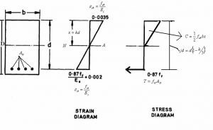
Ultimate Load Method (ULM)
The ultimate load method (ULM) was evolved in 1950 as an alternative to the WSM. The method Relies on the ultimate strength of reinforced concrete at the ultimate load.
The ultimate load is obtained by enhancing the service load by some factor referred to as a load factor for giving a desired margin of safety.
Thus the method is also referred to as the load factor method or the ultimate strength method. The ULM was introduced as an alternative to WSM in the ACI Code in 1956, the British Codes in 1957 and the Indian Code in 1964.
In the ULM method, stress condition at the state of an impending collapse of the structure is analyzed, thus using the non-linear stress-strain curves of concrete and steel. The safety measure in the design is obtained by the use of proper load factor.
This makes it possible to use different load factors under combined loading conditions. It is to be carefully noted that satisfactory strength performance at ultimate loads does not guarantee satisfactory serviceability performance at normal service loads.
Since the method utilizes a large reserve of strength in the plastic region (inelastic region) and of ultimate strength of member, the resulting section is very slender or thin.
This gives rise to excessive deformation and cracking. Also, the method does not take into consideration the effects of creep and shrinkage.
Also, read: Piling for Foundation | Use of Pile Foundation | Characteristics of Pile Foundation
Merits of ULM (Advantage of Ultimate Load Method
While the working stress method uses only the nearly linear part of the stress-strain curve, the ULM uses the actual stress-strain curve fully. In other words, the stress block parameters are defined by the actual stress-strain curve.
- The load factor gives the exact margin of safety against collapse.
- The method allows using different load factors for various kinds of loads and the combination thereof.
- The failure load calculated by ULM matches using the experimental results.
- The method relies on the ultimate strain since the failure criteria.
- The method utilizes the reserve of strength in the plastic region.
Also, read: Dynamic Vs Kinematic Viscosity (Difference & Definition)
Demerits of ULM (Disadvantage of Ultimate Load Method)
The method does not take into consideration the serviceability criteria of deflection and cracking.
The use of high strength reinforcing steel and concrete results in an increase of deflection and crack width.
The method does not take into consideration the effects of creep and shrinkage.
In the ULM, the distribution of stress resultants at the ultimate load is taken as the distribution at service loads magnified by the load factor(s).
This is erroneous since significant redistribution of stress resultants takes place as the loading is increased from service loads to ultimate loads.
To summarise, the ultimate load method ensures safety at ultimate loads but disregards the serviceability at service loads.
Also, read: What Is Bulkage of Sand (Fine Aggregate )
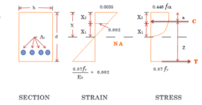
Limit State Method (LSM)
We have seen that while the WSM gives a satisfactory performance of the structure at working loads, it is unrealistic at the ultimate state of collapse.
Similarly, while the ULM provides a realistic assessment of safety, it does not guarantee satisfactory serviceability requirements at service loads.
An ideal method is the one that takes into account not only the ultimate strength of the structure but also the serviceability and durability requirements.
The newly emerging ‘limit state method’ of design is oriented towards the simultaneous satisfaction of all these requirements.
In the limit state method, a structure is designed for safety against collapse (i.e., for ultimate strength to resist ultimate load) and checked for its serviceability at working loads, thus rendering the structure fit for its intended use.
Thus, the LSM includes consideration of a structure at both the working and the ultimate load levels with a view to satisfying the requirements of safety and serviceability.
The European Committee for Concrete (CEB) and the International Federation for Prestressing (FIP) were amongst the earliest to introduce the philosophy of limit state method, which is reliability-based in concept.
‘Recommendations for an International Code of Practice for Reinforced Concrete’ known as the blue book was published in 1963 by CEB and the complimentary report ‘International Recommendations for the Design of Concrete Structures’ known as red book, was published in 1970 by CEB along with RP.
These were subsequently revised by CEB-FIP as the ‘Model Codes for Concrete Structures’ as a model for national Codes to follow.
The LSM was introduced in the British Code in 1973 and the Indian Code in 1978. However, in the United States, it was introduced in 1971 in a slightly different format of ‘strength and serviceability design.’
The acceptable limit of safety and serviceability requirements. Before failure occurs, it is called a limit state.
A limit state is a state of impending failure, beyond which a structure ceases to perform its intended function satisfactorily, in tennis of either safety or serviceability. i.e., it either collapses or becomes unserviceable.
The purpose of the design is to achieve acceptable probabilities that the structure won’t become unfit for the use for which it’s blended. That’s. It will not reach a limit state.
As per IS 456: 2000. All limit states (see § 2.5) shall be considered in the design to ensure an adequate degree of serviceability and safety.
In general, the structure will be designed on the basis of the most critical limit state and will be {checked|assessed} for other limit states.
To make sure the above objectives, the design ought to be based on feature Values for substance strengths and applied loads, which take into account the variations in the material strengths and also at the loads to be supported.
The characteristic values should be determined by statistical data when available; in which these data aren’t available, they need to be dependent upon experience.
The’design values’ are derived from the characteristic values through the utilization of partial safety factors, one for material strengths and another for loads.
Also, read: Soundness of Cement Test
Difference Between Working Stress Method and Limit State Method
| Working Stress Method | Limit State Method |
|---|---|
| Working stress method is also known as the plastic method | Limit State method is also known as the Elastic design |
| Working stress method base on an elastic theory which assumes that steel and concrete are elastic and the stress-strain curve is linear for both | The limit state method is base on the actual stress-strain curves of steel and concrete. For concrete the stress-strain curve is non-linear. |
| Within this method, the factor of safety is put on the yield stresses to get permissible stresses. | In this method, partial safety factors are applied to get a design worth of stresses. |
| In this method not consider the safety factor | Working loads obtain limit State MethodLimit State Method are obtained by Working loads into partial safety. |
| The exact margin of safety isn’t known. | The exact margin of safety is known. |
| This method gives more large, sections, therefore less economical. | This method is more economical since it gives thinner sections. |
| This method assumes that the actual loads, permissible pressures and factors of safety have been understood. So it’s called a deterministic method. | This way is based upon the probabilistic approach that depends upon the real data or expertise, thus it’s referred to as a non-deterministic method. |
| Workin stress method is based method of R.C.C Design. | Limit state method is based method of R.C.C Design. |
| In working stress method, the material follows Hooke’s law as stress is not allowed to cross the yield limit. | Limit state method, stress is allowed to cross the yield limit. |
What Is Rcc Design Method?
There are three methods of structural design, i.e. working stress, limit state and ultimate load method of structural design. These design methods are used for reinforced concrete as well as steel structure design.
Working Stress Method
Working Stress Design Method is a method used for the reinforced concrete design where concrete is assumed as elastic, steel and concrete act together elastically where the relation ship between loads and stresses is linear.
What Is WSM and LSM?
The cardinal difference between Working state method (WSM) and Limit State method (LSM) is: WSM is an elastic design method whereas LSM is a plastic design method. Hence the “moment-rotation” capacity of beam, for example, is utilized making the design more economical.
What Is Working Stress Method in RCC?
Working Stress Method is the traditional method of design not only for Reinforced Concrete but also for structural steel and timber design. The stresses under the working loads are obtained by applying the methods of ‘strength of materials’ like the simple bending theory.
Working Stress Method of Design Definition
Working Stress Design Method is a method used for the reinforced concrete design where concrete is assumed as elastic, steel and concrete act together elastically where the relation ship between loads and stresses is linear .
Which Is an Advantage of Working Stress Method?
- It is simple, both in concept as well as in application.
- It is reasonably reliable.
- It is essential to have a knowledge of WSM, since it forms a part of LSM. IS:456-2000 has incorporated LSM and WSM. But the concept of WSM is retained for checking serviceability states of deflection and cracking.
What Are the Disadvantages of Working Stress Method?
Working stress method does not give reasonable measure of strength, which is more fundamental measure of resistance than is allowable stress. Another drawback in working stress method is that safety is applied only to stress level. Loads are considered to be deterministic (without variation).
Difference Between LSM and WSM
Working Stress method is the old way of designing, in present era structures are generally designed using Limit State Method. In WSM concrete is considered elastic whereas in LSM concrete is generally assumed as plastic.
Ultimate Load Method:
The ultimate loads are obtained by increasing the working/service loads suitably by some factors. These factors which are multiplied by the working loads to obtain ultimate loads are called as load factors. These load factors give the exact margins of safety in terms of load.
Ultimate Stress Design Method
Ultimate Strength Design method is used extensively and almost exclusively in many countries for structural design practice .The Working Stress Design (WSD) method designs RC sections assuming them to be within their elastic limits, where stresses are proportional to strains. Large margins or factors of safety are assumed on material strengths to ensure such behavior.
What Is the Ultimate Load Method?
In this method, the structural element is proportioned to withstand the Ultimate Load which is obtained by enhancing the service load by some factor referred to as load factor for giving a desired margin of safety.
Suggested Read –
- Pile Cap Design Example
- Difference Between One Way Slab and Two Way Slab | What is Slab
- What Is Glass Fiber Reinforced Gypsum | Applications of GFRG | Disadvantages of The GFRG Panel
- What Is Unit Weight | What Is Density | What Is Unit Weight Material | Unit Weight Building Materials
- Density of Cement Sand and Aggregate | Cement Density | Sand Density | Aggregate Density | list of Density
- Prismatic Compass Survey Vs Surveyor Compass. | Least Count of Prismatic Compass & Surveyor Compass

I like it when folks come together and share
opinions. Great website, continue the good work!
Thank you very much. Very knowledgeable. Appreciate your efforts, keep it up!
Like!! I blog quite often and I genuinely thank you for your information. The article has truly peaked my interest.
I’ve learn some excellent stuff here. Certainly value bookmarking for revisiting.
I surprise how so much attempt you put to create this kind of fantastic informative website.
Nice article Dear
Thanks
I just like the helpful info you supply to your articles.
I’ll bookmark your blog and check again right here regularly.
I am somewhat sure I’ll be told many new stuff right right here!
Good luck for the following!
Thanks