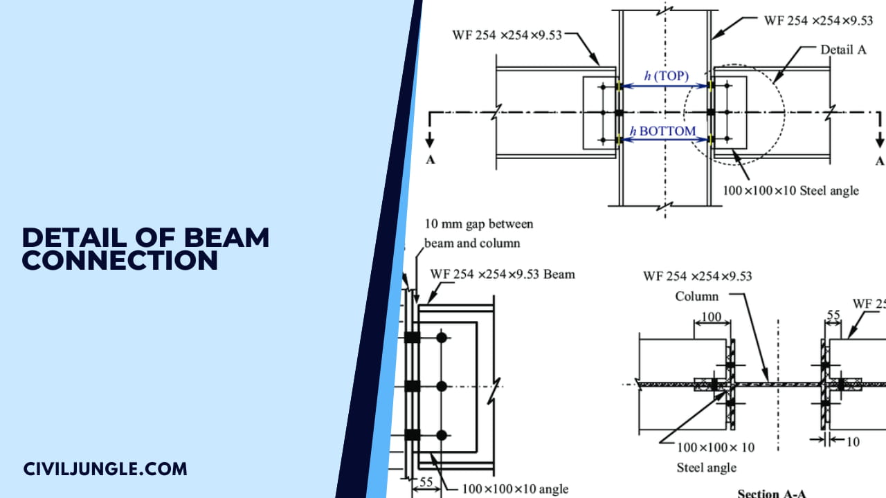
Detail of Beam Connection
Important Point
Beams are connected to main beams or into the columns. The design of these connections is more important -since the failure of connection is more catastrophic than the failure of the beam section.
In this chapter different types of a beam, connections are explained.
As discussed in IS: 800-1984 recognizes the following three types of steel framework construction, depending upon the type 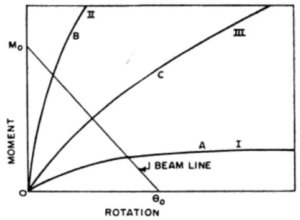
- Simple Framing (curve I)
- Semi-Rigid Framing (curve III),
- Rigid Frame Construction (curve II)
- The typical moment-rotation curves for the three types of framing (or connections) are shown in Fig.
Simple Framing Connection

Simple framing is the one where rotational restraint at the ends of the members is as little as practicable, and in consequence, the structure may, for the purpose of design, be assumed as pin-connected.
For beams, simple framing provides only shear transfer at the ends.
The design of simply supported beams under the working stress method uses this type of connection, while simple framing is not used in plastic design.
One may consider the framing Simple if the original angle between intersecting pieces may change up to 80% of the amount it would theoretically change if frictionless hinged connections could be used
Also, read: What is Bitumen And Bitumens Types
Semi-Rigid Framing Connection

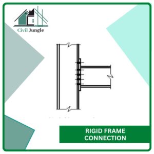
Rigid frame construction is the one where full continuity is provided at the connections so that original angles between the intersecting members are held virtually constant, i.e., with rotational restraint of the order of 90% or more of that necessary to prevent any angle change.
Such connections give the greatest rigidity and economy in the weight of steel used when applied in appropriate cases. Such connections are used under both the working stress and plastic design methods.
Rigid Frame Connection
Semi-rigid framing is the one where rotational restraint is between 20 and 90% of that necessary to prevent any relative angle change.
The semi-rigid connections develop less than the full moment capacity of the connected members.
With semi-rigid framing, the moment transmitted across the joint is neither zero (or a small amount) as in simple framing, nor is it the full continuity moment as assumed in the elastic rigid-frame analysis.
Because of the difficulty of evaluating the degree of restraint, semi-rigid connections are not used in plastic design and are rarey used in working stress design.
Actual connections are neither completely rigid nor completely flexible, and can be classified on the basis of the ratio of the moment developed by the connections to the full moment capacity of the connected member, expressed as a percentage.
As stated above, the approximate percentages for simple connections are from 0 to 20, for a semi-rigid connection from 20 to 80, and for a rigid connection from 80 to 90. The percentage of a particular connection must be determined by actual tests.
Also, read: Type of Stair | Stairs Parts Names & Details
Type of Steel Beam Connection
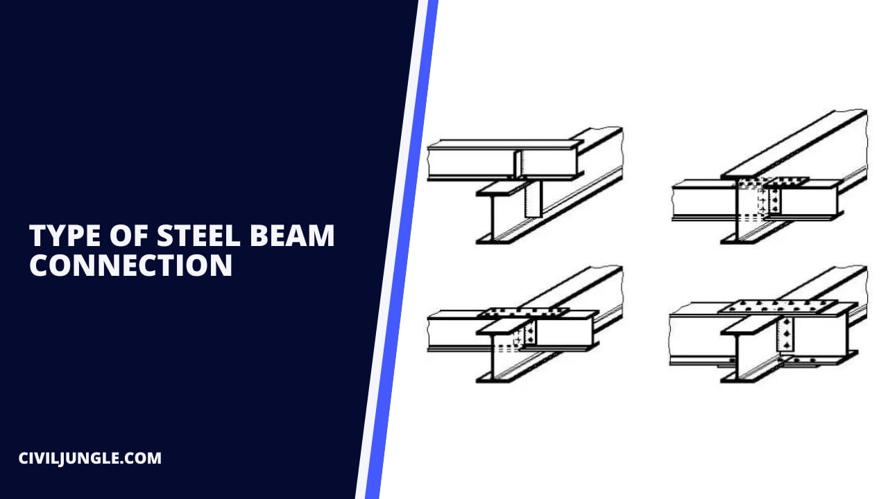
- Riveted Beam Connection
- Bolt Beam Connection
- Welded Beam Connection
1. Riveted Beam Connection

Here, the different types of riveted beam connections are as follows.
- Simple Beam Connections for Riveted
- Riveted Framed Connection
- Riveted Seated Connection
- Riveted Unstiffened Seated connection
- Riveted Stiffened Seated connection
- Moment Riveted Resistant or Rigid Connection
Let’s go we are going a detailed knowledge of simple beam connection for reinvented and moment riveted resistant connection.
1.1. Simple Beam Connections for Riveted
In this connection, two more types of beam riveted connections are as follows in detail please look at that.
1.1.1. Riveted Framed Connection
A framed connection is the one when a beam is connected to a girder or a stanchion by means of two angles placed on the two sides of the web of the beam, as shown below fig. no-1
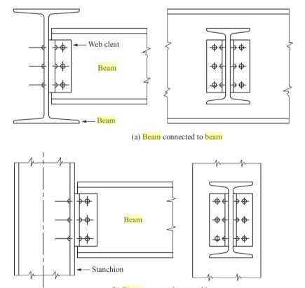
Riveted Framed connection Fig No-1
When the beams intersect and are attached to other beams so that flanges of both are at the same elevation, as shown below fig. no-2 (a), (b), the beams framing-in have their flanges coped or cutaway.
Riveted Framed connection at the s
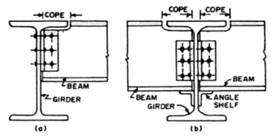
angle level Fig No -2
The loss of section is primarily loss of flange that carries little shear so that normally rope results in little loss of strength.
In framed connections, an angle shelf is sometimes used to support the connecting beam during the erection, simply to facilitate the process (as shown below fig. no-1), though the angle shelf is not an integral part of the connection and may be removed after the connection process is over. 3
Also, read: Procedure for Rcc Concrete
1.1.2. Riveted Seated Connection
When a beam is connected to the flange (or the web) of a steel stanchion, the width of the flange (or the depth of the web) may be insufficient to accommodate the connecting angles. In that case, framed beam connections are not suitable, and seated beam connections are preferred.
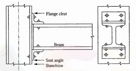
In its simplest form, a seated connection is the one in which a horizontal angle with its horizontal leg at its top is used to receive the beam on it, as shown in as per below fig; in such as a case it is called unstiffened seat connection.
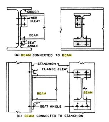
Seated Connection
In addition to the seat angle, a web cleat is provided when the beam is connected to a beam (as per above fig ) while a flange cleat is used when the beam is connected to a stanchion.
The angle cleats (i.e. web cleat or flange cleat) are essential parts of seated connections because they keep the beam stable in a vertical position and prevent it from lateral buckling.
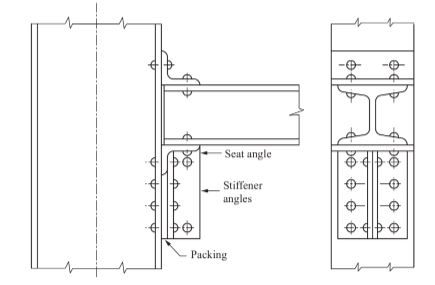
When the reaction to be transferred by the beam is so large that the scat angle cannot support it, then the horizontal leg of the seat angle is stiffened by means of one or two stiffener angles, as shown in as per below fig.
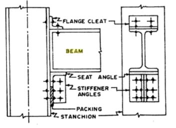
StiffeSeated Connection
The stiffener angles should be tightly fitted under the seating angle and suitable packing should be provided, as shown in as per above fig.
Seated connections require more space in the vertical direction, and due to this, they are not commonly used for connecting the beam to a beam. Seated connections are more suitable for connecting the beam to either the flange or to the web of a steel stanchion.
Similarly, a framed connection is not suitable for connecting a beam to the web of a column because of the space limitation on either side of the beam.
Also, read: What Is Honeycomb In Concrete | Cause | Cure | Type of Grouting
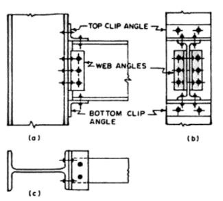
1.2. Moment Resistant or Rigid for Riveted Connection
Up to this stage, we have discussed simple connections that transfer shear only, and permit full rotation of the beam. Some times, it may be required to transmit moments also, in addition to shears, such as in building frames.
As discussed earlier, there are two types of constructions which permit the transfer of moments, either fully or partially:
- Rigid construction and
- Semi-rigid construction.
In both the above types of construction, the connections or joints are so designed that they permit the transfer of moment in addition to shear.
Based on the magnitude of the moment to be transferred, these may be two types of connections :
- Small moment resistance connections
- Large movement resistance connections
Small moment resistance connections
Large movement resistance connections
2. Bolt Beam Connection

Here, the different types of bolt beam Connection are as follows.
- Simple Beam Bolt Connections
- Bolt Framed Connection
- Bolt Seated Connection
- Bolt Unstiffened Seated Connection
- Bolt Stiffened Seated Connection
- Moment Resistant or Rigid for Bolt Connection
- Sami Regid Bolt Connection
Let’s go we are going a detailed knowledge of simple beam connection for reinvented and moment bolt resistant connection.
2.1. Simple Beam Blot Connections
In this connection, two more types of beam bolt connections are as follows detail, please look at that.
2.1.1. Bolt Framed Connections
When the end shear to be transferred is less, it is possible to connect the beam to the main beam or to the column using cleat angles, as shown in also show fig. (a) and (b).
Framed Connections
If the flanges of the beam to be connected are at the same level, the flanges of the connecting beam are cut, as shown below fig,
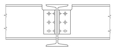
Framed Connections if flanges are at the same level
This will not pose any structural problem since at the end of simply supported beams moment is zero, and shear strength depends mainly on the strength of the web.
Also, read: Difference Between Flexible Pavement and Rigid Pavement | What is Pavement | Type of Pavement
2.1.2. Bolt Seated Connection
In this method, two different parts one is Bolt Unstiffened Seated Connection and other Bolt Stiffened Seated Connection doth are detailed as follows.
2.1.2.1. Bolt Unstiffened Seated Connection
When shear force are larger, the depth of the cleat angle required for framed connection may be more than what can be provided at the available space. In such cases of the seat, angles are connected to this column over which beam rests.
At top cleat, angles are provided to prevent the lateral displacement of the beam after positioning it over seat angle also shows in below fig. a typical such connection.
Unstiffened Seated Connection
2.1.2.2. Bolt Stiffened Seated Connection
If shear force to be transferred at the beam is still large, the seat angle may fail. To strengthen it, a stiffener angle can be provided, as shown in as per below fig. Such connections are known as a stiffened seated connection.
Stiffened Seated Connection
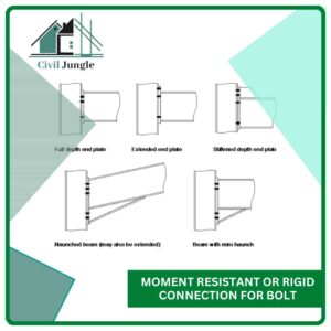
2.2. Moment Resistant or Rigid for Bolt Connection
In this the joint is designed to resist end shear as well as moment. such supporters may be treated as fixed ends, since they do not permit any rotation at the end.
2.3. Sami Regid Bolt Connection
In this type rotation of the end is partially restrained. In other words, the connections are designed to transfer shear and part of fixed end moment.
Also, read: Core Cutter Method | What is Compaction of Soil
3. Moment Resistant or Rigid Connection for Bolt
Here, the different two different types of moment resistant are as follows.
-
- Clip-Angle or Split Beam Connection
- Bracket Connection
3.1. Clip Angle Connection
This type of connection may be used at the end of the moment to be transferred in the end is small as per below fig. shows a typical clip angle connection.
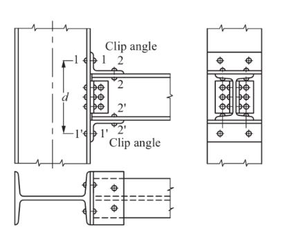
Clip angle connection
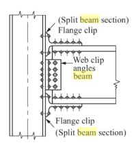
Split Beam Connection
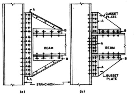
3.2. Bracket Connection
If the moment to be transferred through this connection is large such connections are used as per below fig. shows a typical bracket connection.
Bracket connection
Also, read: What Is Cement | Type of Cement
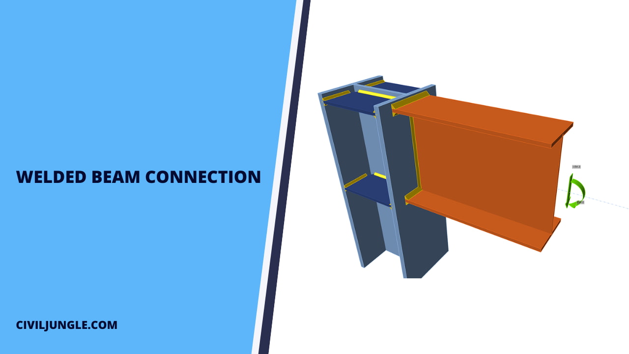
Welded Beam Connection
Here, the two different connection are as follows.
- Simple Welded Beam Connections
- Moment Welded Resistant or Rigid Connection
Beams may be connected to the supporting beam or to the supporting column by welding. In fact, welded connections are used more commonly instead of bolted connections.
The end of the beam may be designed to transfer the only shear to the supporting structure by
- Framed connection
- Unstiffened seated connection
- Stiffened seated connection.
The ends of the beam may be designed to transfer shear as well as moment by welded connection.Such connections are known as moment resistant connection.
Also Read: Different Types of Washers for Bolts
1. Simple Welded Beam Connections
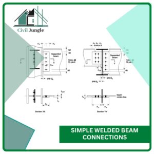
In this connection three different parts. In this part are as follows.
- Welded Framed Connection
- Welded Unstiffened Seated Connection
- Welded Stiffened Seated Connection.
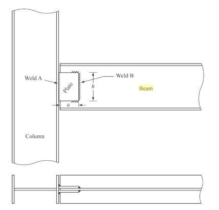
1.1. Welded Framed Connection
The direct fillet or butt welds explained in need accurate lengths and edge finishes, which may be quite difficult to achieve. Instead of these connections, framed connections may be adopted, which are flexible.
The following two types of framed connections are possible.
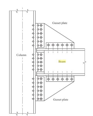
1.1.1. Double-Plated Framed Connections
Instead of two plates may be used for the connection beam and the supporting member to get more flexibility in the connection. The plate to are connected to the web of the beam by shop welding.
1.1.2. Double Angle Framed Connections
Instead of two angles may be used for the connection beam and the supporting member to get more flexibility in the connection. The angles to are connected to the web of the beam by shop welding.
Double Plated Welded Framed Connections
Double Angle Framed Connections
Also, read: Test for Compressive Strength of Brick | Water Absorption | Dimensions Test
1.2. Welded Unstiffened Seated Connection
When the end reaction to be transferred is low, welde unstiffened seat connection can be used. The beam is placed over a seat welded and angle
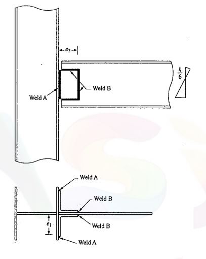
1.3. Welded Stiffened Seated Connection.
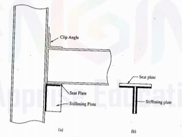
Welded Stiffened Seated Connection
As per a typical stiffened seat connection. The seat used can be a split two-plate, or I beam forming a T-section.
The seat plate thickness isn’t less than the thickness of the flange of the beam, and the thickness of the stiffening plate is not less than the thickness of the web of the beam.
Seat plate and stiffening plates are welded, as shown below, as above Welded Stiffened Seated Connection – a side
The width of the seat plate is kept equal to the width of the flange of the beam. The same size plate can be used as a stiffening plate. Weld looks like a T-section, as shown below, as above Welded Stiffened Seated Connection – b side.
2. Moment Welded Resistant or Rigid Connection
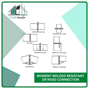
Moment connections are classified as rigid and full/partial strength connections. For rigid connections, end plate and welded connections are classified according to the rotational rigidity which is defined according to the earthquake regulations depending on the ductility level.
Stiffened Seated Connection
- In multistory braced frames, simple, or Type PR connections of beams to columns are often made using beam seats.
- These may be made with heavy angles or, if loads are large, a stiffened seat may be used. The stiffened seat is usually made by welding two plates in the form of a tee.
Beam Connection Design Software
There are several software programs available for beam connection design. Here are a few commonly used ones:
- RISAConnection: RISAConnection is a popular software for designing steel connections. It allows you to design a wide range of beam-to-beam and beam-to-column connections, including shear connections, moment connections, and bracing connections. RISAConnection provides comprehensive design reports, detailing the connection capacity checks and allowing customization of connection details.
- IDEA StatiCa Connection: IDEA StatiCa Connection is another widely used software for the design of steel connections. It offers advanced analysis and design capabilities for various connection types, such as moment-resisting, pinned, and bracing connections. IDEA StatiCa Connection integrates with popular structural analysis software, enabling seamless transfer of data and results.
- RAM Connection: RAM Connection, developed by Bentley Systems, is a powerful software for steel connection design. It provides a range of connection design options, including moment connections, bracing connections, and shear connections. RAM Connection integrates with structural analysis software like RAM Structural System and STAAD.Pro for streamlined analysis and design workflows.
Beam Connection Types and Details
Beam connections are structural elements used to join two or more beams together, allowing them to transfer loads and distribute forces effectively. The type of beam connection used depends on various factors, including the structural requirements, loads, and design preferences. Here are some commonly used beam connection types:
- Welded Connections: In welded connections, beams are joined by welding the ends or flanges together. This type of connection provides excellent strength and rigidity.
- Bolted Connections: Bolted connections involve using bolts, nuts, and washers to join beams. This type of connection allows for easy assembly, disassembly, and modification.
- Riveted Connections: Although less common nowadays, riveted connections were widely used in the past. They involve driving a metal rivet through aligned holes in the beams and then deforming the end to form a permanent connection. Riveted connections offer good strength and durability.
Steel Beam Connection Details
Steel beam connection details refer to the specific design and construction methods used to connect steel beams together. These connections play a crucial role in transferring loads and ensuring the stability and structural integrity of the overall steel structure.
Beam Connection Design Guidelines
When it comes to designing beam connections, there are several guidelines to consider to ensure the structural integrity and stability of the overall system. Here are some general guidelines to keep in mind:
- Load Analysis: Begin by understanding the loads acting on the beam and the connection. Consider both the applied loads (e.g., dead loads, live loads) and any anticipated dynamic loads (e.g., wind loads, seismic loads). The connection design should be able to handle these loads safely.
- Material Selection: Choose appropriate materials for the beam and the connection components. Consider factors such as the strength, ductility, and corrosion resistance of the materials based on the environmental conditions and the load requirements.
- Connection Type: Select the most suitable connection type based on the specific project requirements and structural system. Common connection types include bolted connections, welded connections, and composite connections. Each type has its advantages and limitations, so choose the one that best suits your design criteria.
Beam Connection Calculation Methods
Beam connections are important structural elements used in the construction of various types of buildings and bridges. The calculation methods for beam connections depend on the type of connection and the design requirements. Here are some commonly used methods for calculating beam connections:
- Bolted Connections: Bolted connections involve using bolts to join the beams together. The design of bolted connections typically follows established codes and standards such as the American Institute of Steel Construction (AISC) Manual or Eurocode.
- Welded Connections: Welded connections involve joining beams by welding the connecting plates or members. The design of welded connections also follows relevant codes and standards, such as the AISC Manual or Eurocode. The calculation methods for welded connections include determining the required weld size, checking the weld strength, and considering the applied loads, material properties, and design factors of safety. Weld design also considers factors such as the type of weld, joint configuration, and welding procedures.
- Moment Connections: Moment connections are used to transfer bending moments between beams. The design of moment connections requires evaluating the capacity of the connection to resist bending moments. Methods such as the double angle cleat connection, end plate connection, or flange plate connection are commonly used.
Beam to Beam Connection
A beam-to-beam connection is a welded joint between two beams. Typically, one beam acts more like a vertical column where the other protrudes horizontally off of it. This is a common structural support found in buildings and bridges.
Framed Connections in Steel
A framed connection is a shear-resisting steel connection made by welding or bolting the web of a beam to the supporting column or girder with two angles or a single tab plate. Seat angle carries shear load.
What Is Seated Connection?
These connections are split into two main groups: Seated connections – where a steel beam is positioned on a seat, similar to that of masonry walls. Framing connections – where the beam is connected to the supporting steel structure through a fitting.
What Is Framed Connection?
Frame connections describe the positioning relationship between member systems. This positioning relationship defines the member orientation and offset of the supported member in relation to the supporting member. Two frame connections are placed when you place the member system, one at each end.
What Is Rigid Connection?
A rigid connection is the link between two bodies which are stiffened and fastened together at their common boundary, and will behave as if their interface was infinitely rigid.
Beam to Column Connection
What is a Beam to Column Connection? According to ‘Jack Moehle’ (Author of Book: Seismic Design of Reinforced Concrete Buildings), the beam to column connection comprises the joint plus portions of the beams, columns and slab immediately adjacent to the joint.
Types of Beam to Beam Connection
For beam to beam connections, there are generally two types, depending on beam geometry. The first type is a primary beam connected to an adjacent secondary beam. The second type is through the use of a beam splice for linearly aligned members.
Types of Steel Beam Connections
Types of Steel Beam Connections
- Bolted framed connections.
- Bolted seated connections.
- Welded framed connections.
- Welded seat connections.
- End plate connections.
- Special connections.
- Simple, rigid and semi-rigid connections.
Like this post? Share it with your friends!
Suggested Read –
- H Beam or I Beam
- Double Reinforced Beam
- Beam Load Calculation Formula
- Largest Roofing Company in America
- Trapezoidal Footing Formula with Calculation
- Total Station in Surveying | Operations | Advantage & Disadvantage | Types
- Difference Between One Way Slab and Two Way Slab | What is Slab
- What Is Honeycomb In Concrete | Cause | Cure | Type of Grouting
- Methods of Design | Difference Between Working Stress Method and Limit State Method
- What Is Structural Settlement | Causes For Structural Settlement | What Is Soil Settlement & Foundation Structural Settlement

Leave a Reply