Importance of Engineering Drawing
Important Point
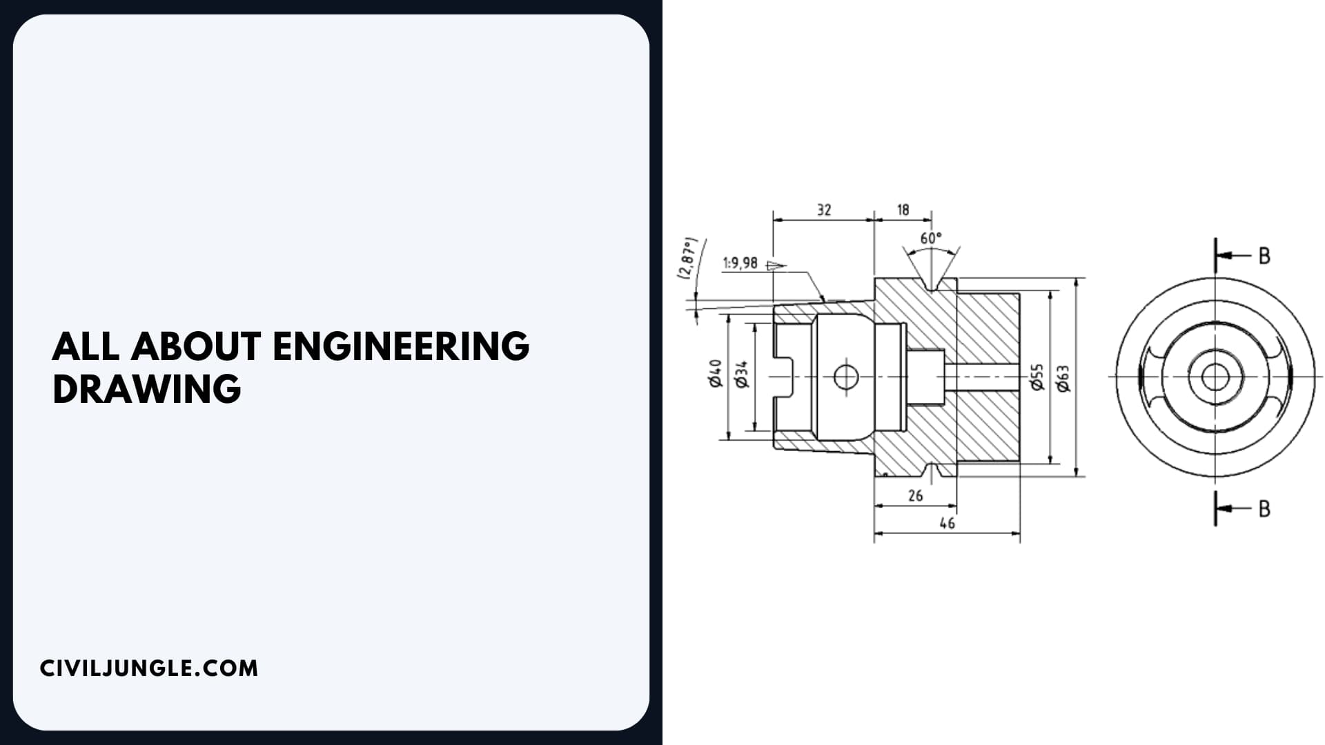
A subcategory of technical drawings is an engineering drawing, which we can define as engineering drawing as a graphical representation with the goal to convey all of the information required to manufacture a product or a component. This is the engineering drawing definition.
Standardized language and symbols are used in engineering drawings. This simplifies the interpretation of the drawings and eliminates the possibility of personal interpretation.
What is Engineering Drawing?
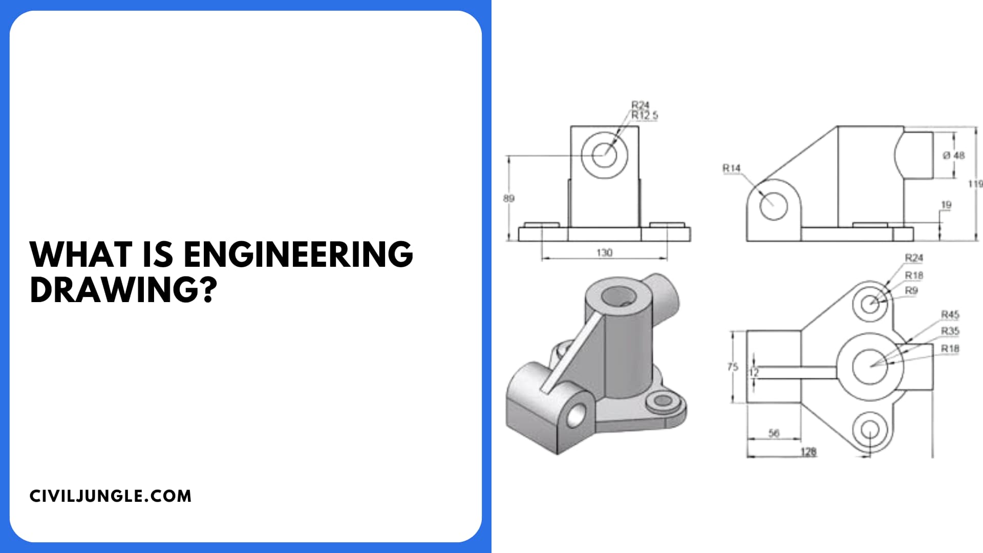
Engineering drawings are detailed diagrams that display all of the details and specifications required to produce a particular object or product. It is a graphical language that communicates ideas and facts, not just a drawing.
An engineering drawing, rather than an image, is used to illustrate the size and shape of a product and can include details such as appropriate variants, load limits, materials, and any other information that may aid in a full understanding of the product.
- Building Layout | How to Building Layout | What Is Method of Layout of Building | Control Lines of Construction | Construction Layout
- What Is Auxiliary Plane | Types of Auxiliary Plane | Types of Auxiliary View | How to Draw Auxiliary View | Drawing Steps for Auxiliary View
- Difference Between Sketching and Drawing | What Are Conceptual Sketches | Architecture Concept Drawing | Types of Drawings for Building Design
- What Is Oblique Drawing | Oblique Drawing Examples | What Is Oblique View | Oblique Projection | Oblique Shape | Cabinet Oblique | What Is Cavalier Drawing
Types of Drawings Instruments [Instruments Used in Engineering Drawing]
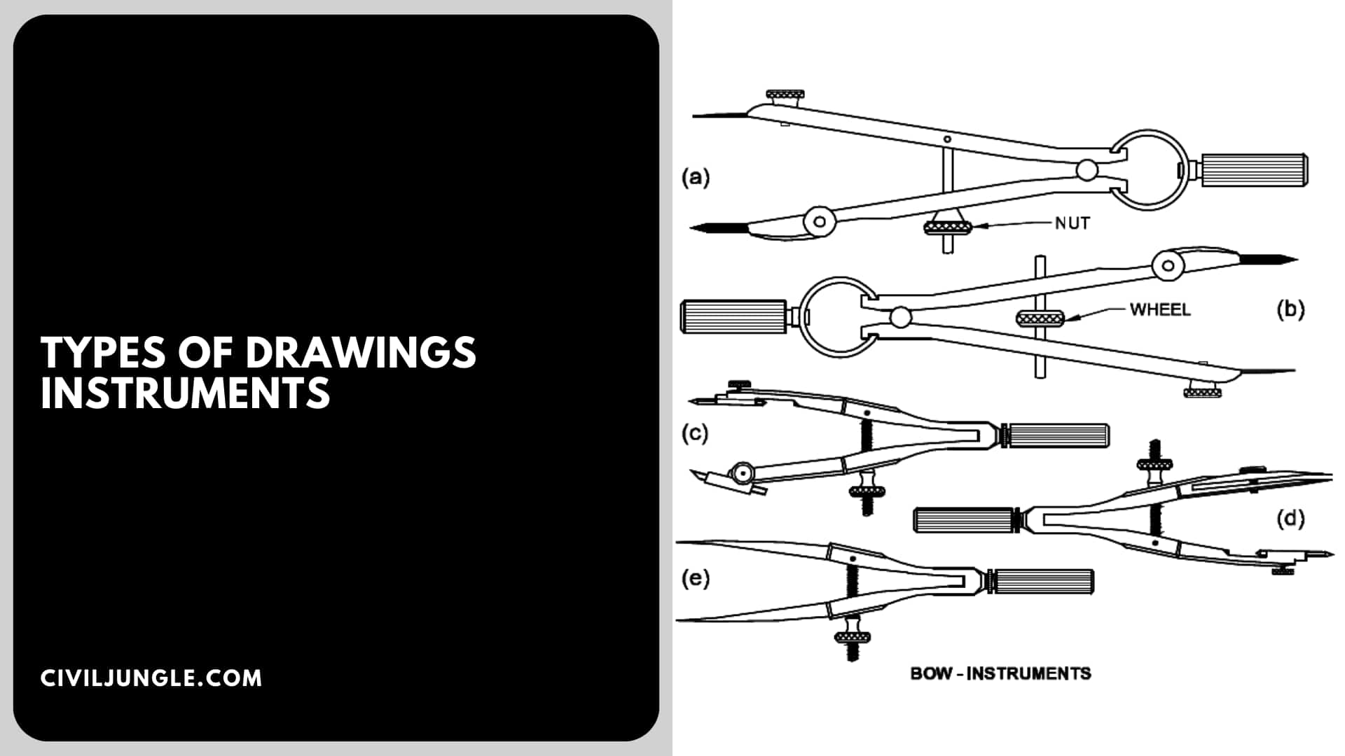
To create tidy and precise drawings, engineering drawing instruments are used. These drawing instruments have specific names and are part of the essential engineering drawing materials.
The standard of the instruments used to prepare the Drawings has a greater impact on the accuracy of the Drawings.
The following is a list of appropriate Drawing Instruments and other materials
- Drawing Board
- T-Square or Drafter (Drafting machine)
- Set Squares
- Protractor
- Drawing Instrument Box
- Drawing Sheet
- Drawing Pencils
- Drawing Pins/Clips
- Compass
- French Curve
- Scales (Ruler)
- Roll & Draw
- Circle Master
- Sharpener
- Eraser
- Duster or Handkerchief
1. Drawing Board
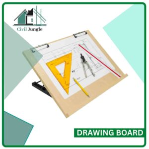
The drawing board is made of 25 mm thick strips of well-seasoned softwood. Two battens are cleated at the back to keep it from warping.
One of the rectangular board’s shorter edges has a perfectly straight ebony edge that is used as a working edge for moving the T-square when making drawings.
Drawing boards come in a variety of sizes. The drawing board you choose is determined by the size of the drawing paper you’ll be using.
The Bureau of Indian Standards (B.I.S.) has proposed the following sizes for drawing boards.
|
Standard Size of Drawing Boards |
|
|
Designation |
Size (mm) |
|
B0 |
1500×1000 |
|
B1 |
1000×700 |
|
B2 |
700X500 |
|
B3 |
500×350 |
|
B4 |
250×350 |
2.1. T-Square
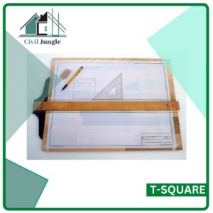
Strong wood is used to make T-squares, which are important engineering graphics instruments and are among the key drawing instruments in engineering drawing.
A T-square is made up of two parts: the stock and the blade, which are connected at right angles by screws and pins.
Set squares are used to draw parallel lines, vertical lines, or inclined lines at 30°, 60° to the horizontal using the working edge of a T-square.
Useful Article for You
- What Is Composite Wood
- What Is the Difference Between a Shower Pan and a Shower Base?
- What Is a Window Panel
- What Is Rebar Made Of
- What Is Crane
- What Is a Frame Structure
- What Is the Measurement for a Queen Size Bed
- What Is Considered Livable Space
- What Is One Way You Can Save Electricity?
- What Is Mdf Mean
- What Is a Bundle of Shingles
- What Is a Gallon of Water Weigh
- What Is Window Sash
- What Is a Sieve Analysis
- What Is the Little Black Diamond on a Tape Measure
- What Is the Difference Between a Bolt and a Screw?
- What Is Overhang
- What Is a Contour Interva
- Foundation in Civil Engineering
- What Is a Spread Footing
- What Is Tile
- What Is Leveling
- What Is Modulus of Rupture
- What Is a Caisson
- What Is a False Ceiling
- Architectural Blueprint Symbols
2.2. Drafting Machine (or Drafter)
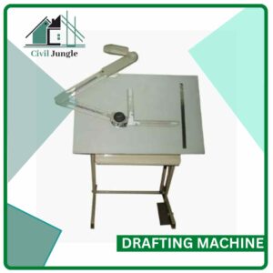
The advantages and uses of T-square, set square, scales, and protractors are combined in a drafting machine.
A screw provided in the Drafter is used to lock one end of the Drafter to the left top end of the Drawing board.
At the other end of the Drafter, an adjustable head with a Protractor is mounted.
The adjustable head is fitted with two blades made of translucent celluloid material that are completely perpendicular to each other.
Parallel, horizontal, vertical, and inclined lines are all drawn with these blades. The blades are often parallel to the board’s edges.
The use of a drafting machine reduces the amount of time it takes to prepare a drawing.
Also, Read: What Is a Field Dry Density Test | Different Types of Field Density Tests
3. Set Squares
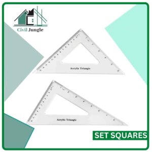
Plastic or celluloid are the most popular materials used to make set squares. They are triangular in shape, with one right-angle triangle as a corner.
A pair of set squares (30°–60°) and 45° (a 45° set square is usually used with a Protractor) make it easier to mark angles.
They’re used to draw lines at 30°, 60°, and 45° angles to the vertical and horizontal.
4. Protractor

Protractors, a crucial piece of engineering drawing equipment, are used to calculate or label angles between 0 and 180 degrees.
They have a semicircular shape (diameter 100mm) and are made of plastic or celluloid, which has a longer life span.
Protractors with a circular shape that can mark and measure from 0 to 360 degrees are also available on the market
5. Drawing Instrument Box

It consists of the following components:
- Large size compasses,
- Large size divider,
- Small size bow pen, bow divider, and
- Lengthening bar.
Also, Read: What Is Pitched Roof | 8 Types of Pitched Roof | Advantages of Pitched Roof
6. Drawing Sheet
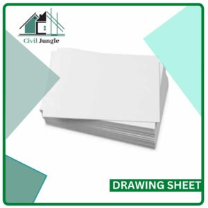
They come in a wide range of colors and textures, and good quality paper with a smooth surface should be chosen for drawings that can be kept for a long time.
The Bureau of Indian Standards (B.I.S.) has given the following sizes for drawing sheets.
| Standard Size of Drawing Sheet | |
|
Designation |
Size (mm) |
|
A0 |
1189 × 841 |
|
A1 |
841 × 594 |
|
A2 |
594 × 420 |
|
A3 |
420 × 297 |
|
A4 |
297 × 210 |
|
A5 |
210 × 148 |
7. Drawing Pencils
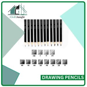
The consistency of the pencil used to create a drawing determines the accuracy and appearance of the drawing.
The lead grade of a Pencil is shown on the Pencil. The abbreviation HB stands for “medium grade.”
Harder pencils are labeled with a value in front of H, such as 2H, 3H, and so on.
Softer pencils are labeled with 2B, 3B, 4B, and so on. A 3B pencil is softer than a 2B pencil, and a 4B pencil is softer than a 3B pencil, and so on.
The letter H or the number 2H may be used to start a drawing. H and HB Pencils are used for lettering and dimensioning.
8. Drawing Pins and Clips

These two are used to fix the drawing sheet in place on the drawing board.
9. Compass

Circles and arcs of circles is done with a compass. The compass has two hinged legs on one hand.
The lower end of one of the legs is fitted with a pointed needle, while the other end has a provision for inserting pencil lead.
The legs of the compass are held straight to draw circles up to 120mm in diameter.
11. French Curve

These have an unusual cross-section and were used to draw small arcs and long splines that a drafter couldn’t draw. They are made of plastic or steel.
11. Scales (Ruler)
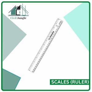
A ruler, also known as a rule or line gauge, is a tool used to calculate distances and/or rule straight lines in geometry, technical drawing, printing, and engineering/building.
For technical drawings, you’ll need to use this tool frequently. The scales come in a variety of materials, including plastic, wood, and steel. A steel rule is commonly used to design engineering drawings.
12 Roll and Draw
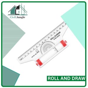
Roll & Draw is an incredibly useful method for easily generating charts and parallel lines. It’s also known as “the best friend of a draftsman.”
It’s also a multipurpose drawing tool that allows you to quickly and easily draw quadrants, triangles, circles, angles, crosshatching, and vertical and horizontal parallel lines in centimeters.
Useful Article for You
- What Is a Grade Beam
- What Is Flooring
- What Is Shoring
- What Is a Bridge Abutment
- What Is a Cold Joint in Concrete
- What Is the Strongest Foundation for a House
- What Is a Well Point
- What Is a Floating Slab
- What Is Grouting
- What Is Rcc Value Day
- What Is a Stair Landing
- What Is Optimum Dry
- What Is a Moment Frame
- What Is Standard Water Pipe Size in Residential
- What Is Flagstone
- What Is a Door Frame
- What Is an Admixture
- What Is a Frost Wall
- What Is Undercoat
- What Is Bituminous Pavement
- What Is Gypsum Board
- What Is a Parapet Wall
- What Is a Monolithic Slab
- What Is Cmu Wall
13. Circle Master

Circle Master is a useful template-type drawing instrument that allows you to quickly draw circles of various radiuses.
It does away with the use of a compass since a circle with a fixed radius can be drawn. It’s a flat or circular plate with various-sized holes punched on the top.
If you try to draw a circle with a radius other than the radius punched, you’ll need to use a different drafting instrument because the radius of a circle can’t be changed.
14. Sharpener

A pencil sharpener is a device that shaves the worn surface of a pencil to sharpen the writing edge.
15. Eraser

An eraser is a tool that is used to remove pencil marks from paper or sheets.
16. Duster or Handkerchief

To clean the paper on which the drawing is being done, a duster or handkerchief is often used. They come in a variety of colors and sty.
Also, Read: What Is a Flight of Stairs | Types of Stairs | How Many Stairs in a Flight | Some Facts About Stairwells
Drawings Instruments
- Drawing sheet.
- Drawing board.
- Mini drafter.
- T square.
- Compass.
- Divider.
- Set squares.
- Clinograph.
- Protractor
- French Curves
- Drawing Templates
- Pencils
- Eraser
- Paper Holders
Engineering Drawing
An engineering drawing, also known as engineering graphics, is a type of instrument drawing that is used to convey information about an object. The process of producing engineering drawings is often referred to as technical drawing or drafting (draughting).
Electrical Engineering Drawing
An electrical drawing is a type of technical drawing that shows information about power, lighting, and communication for an engineering or architectural project.
Engineering Drawing Standard
Conventions are essential for clear, unambiguous written, oral, and graphical communication. Drawings are used by engineers and manufacturing technologists to communicate their ideas and hence good engineering drawings follow conventions which are referred to as drawing standards.
Structural Engineer Drawing
Engineer’s drawings and structural computation documents give details about the structural members required to hold the structure up. The structural engineer interprets the contour plan with the working drawings and determines the height of retaining walls. The higher the wall, the stronger the design must be.
What Is Structural Engineer Drawing?
A full set of blueprints will typically contain detailed floor plans, exterior elevations, residential front perspective, foundation and basement plans, house & detail cross sections, floor structural supports, and roof framing plans.
Cad Technical Drawings
Technical drawing, also known as drafting or draughting, is the act and discipline of composing plans that visually communicate how something functions or has to be constructed. The 2D CAD system allows a copy of the original to be modified, saving considerable time.
Structural Shop Drawings
Shop drawings are typically a set of drawings required for prefabricated components. Shop drawing includes dimensions, manufacturing standards, fabrication. They contain more details compared to construction documents. Obtaining architectural approval is only a small part of what a quality shop drawing provides.
What is Engineering Drawing?
An engineering drawing is a type of technical drawing used to define the requirements for engineering products or components. It may also describe the process of making the item, may be used to convey engineering ideas during the design process, or may provide a record of an existing item.
Mechanical Engineering Drawing
Mechanical engineering drawings are technical and skilled drawings that help define and illustrate specific mechanical requirements and processes, often utilizing various engineering graphics tools. They are engineering drawings specifically for mechanical purposes. These technical drawings help communicate problems and solutions that mechanical engineers experience.
Mechanical Drawing
Mechanical systems drawing is a type of technical drawing that shows information about heating, ventilating, air conditioning and transportation around the building (Elevators or Lifts and Escalators). It is a powerful tool that helps analyze complex systems.
Technical Drawing
A technical drawing, also known as an engineering drawing, is a detailed, precise diagram or plan that conveys information about how an object functions or is constructed. Engineers, electricians, and contractors all use these drawings as guides when constructing or repairing objects and buildings.
Iso Standard Drawing
ISO 128 is an iso standard for the general principles of presentation in technical drawings, specifically the graphical representation of objects on technical drawings. ISO 13567 is a CAD layer standard.
Mechanical Drawing Tools
| Drawing Tools | User | Areas of Uses |
| Mechanical Pencils |
|
|
| Clutch pencils |
|
|
| Technical pens |
|
|
| Rulers |
|
|
| Compass |
|
|
| Drawing boards |
|
|
| Erasers |
|
|
| Sharpeners |
|
|
Importance of Engineering Drawing
Typically, the purpose of an engineering drawing is to clearly and accurately capture all geometric features of a product or component so that a manufacturer or engineer can produce the required item.
Instruments Used in Engineering Drawing
- Drawing sheet
- Drawing board
- Mini drafter
- Eraser
- Pencils
- Protractor
- French curves
- Templates
- Paper Holders
- Set squares
- Compass
- Divider
Engineering Drawing Tools
- Drawing tools. Pencil. Drafting board. T-square. Drafting machine. French Curves. Rulers. Compass. Templates. Perspective machines.
- Drawing materials. Drafting paper. Thick draft paper. Cloth. Tracing paper. Tracing tube. Inks. Dry transfer.
Like this post? Share it with your friends!
Suggested Read –
- Parts of Stairs Labeled
- H-Beam vs I-Beam | What Is H-Beam | What Is I-Beam
- Tension Vs Compression | What Is Tension & Compression
- What Does Parapet Mean | Types of Parapet Wall | Uses of Parapet Wall
- 15 Difference Between Bridge and Culvert | What Is Bridge | What Is Culvert
- Cinder Block Vs Concrete Block | What Is Cinder Blocks | What Is Concrete Blocks
- What Is Reinforced Brick Masonry | Construction of the Reinforced Brick wall | What Is Reinforced Brick Concrete
- Tributary Area | Tributary Area Examples | Tributary Width | Tributary Load | Tributary Area in Columns | Overview of Tributary Area
- What Is Mat Foundation | Mat Building | Advantage and Disadvantage of Mat Slab Foundation | Types of Mat Foundation | Where Mat Foundation Is Used

Amazing list of engineering drawing requirement to draw a final dimensional figure. I loved french curve i never see it before. Thanks for this list.