What Is Isometric Projection?
Important Point
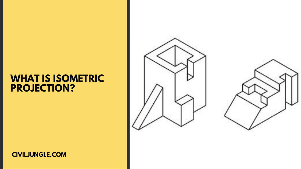
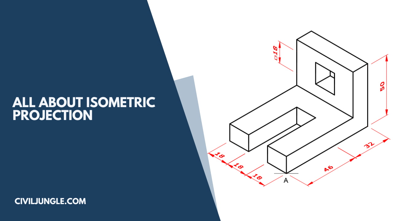
Isometric projection, which answers the question of what is isometric view, is a method for visually representing three-dimensional objects in two dimensions in technical and engineering drawings.
It is an axonometric projection in which the three coordinate axes appear equally foreshortened and the angle between any two of them is 120 degrees.
Pictorial projections are utilized for presenting ideas that might be easily understood by persons, even without technical knowledge and training of multi-view drawing.
The Pictorial drawing shows several faces of an object in one view, approximately as it appears on the eye.
Isometric Projection
Isometric projection is a method for visually representing three-dimensional objects in two dimensions in technical and engineering drawings. It is an axonometric projection in which the three coordinate axes appear equally foreshortened and the angle between any two of them is 120 degrees.
Principle of Isometric Projections
1- Principle of Isometric Projections
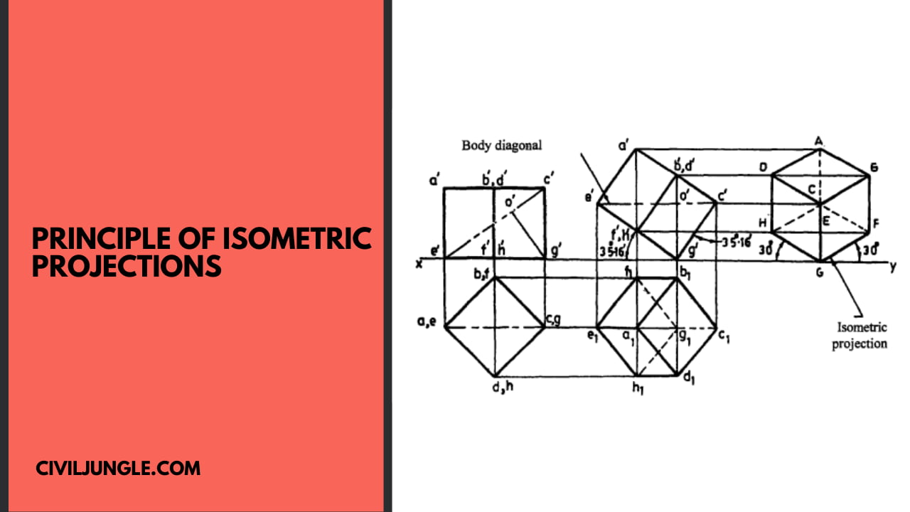
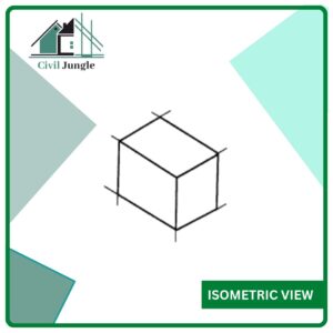
It’s a pictorial orthographic projection, or isometric projection in engineering drawing, of an object where a transparent cube containing the object is tilted before one of those solid diagonals of the cube becomes perpendicular to the vertical plane along with the three axes are equally inclined to this vertical plane.
The isometric projection of a cube in steps is shown in the below figure-1. Here ABCDEFGH is the isometric projection of the cube.
The front view of this cube, resting on one of its corners (G), is the isometric projection of the cube. The isometric projection of the cube is reproduced shown in the below figure-2.
Also, read: What Is Crane | Different Types of Cranes
Useful Article for You
- What Is a Contour Interval
- What Is Tile
- What Is the Difference Between a Shower Pan and a Shower Base?
- What Is a Window Panel
- Type of Arch
- What Is a Frame Structure
- What Is the Measurement for a Queen Size Bed
- What Is Considered Livable Space
- What Is One Way You Can Save Electricity?
- What Is Mdf Mean
- What Is a Bundle of Shingles
- What Is a Gallon of Water Weigh
- What Is SuperelevationWhat Is Overhang
- What Is Sand Blasting
- What Is a Span Bridge
- What Is the Little Black Diamond on a Tape Measure
- What Is a Louvered Door
- What Is a Spread Footing
- What Is Leveling
- Different Types of Beam
- What Is Pedestal
- What Is Plumbing Fixtures
- What Is Slab Construction
- What Is Calacatta Quartz
- What Is Auxiliary View
- Sheepsfoot Roller
- Live Load Vs Dead Load
- What Is 1 Flight of Stairs
- What Is Refractory Cement
- Dry Pack Concrete
- What Is Luminous Flux Vs Lumens
- What Is a Frost Wall
- What Is an Undercoat
- What Is Road Pavement
- Arch Foundation
- What Is a Stair Landing
- What Is Stone Masonry
- What Is a Spandrel Beam
- What Is Pier and Beam Foundation
- What Is Levelling
- What Is a Pile Cap
- What Is a Mat Foundation
- What Is a Floating Slab
- What Is the Purpose of Foundation
- What Is Modulus of Rupture
- What Is a Flush Door
- What Is Residential Construction
- What Is the Best Foundation for a House
- What Is a Benchmark in Surveying
- What Is a Engineering Drawing
- What Is an Admixture
- What Is a Monolithic Slab Foundation
- What Is the Standard Size Water Supply Line
- What Is the Difference Between Tension and Compression?
- What Is a Tremie
- What Is Tributary Area
- What Is Shoring Construction
- What Is a Cason
- What Is Wall Putty
- What Is the Difference Between Mortar and Concrete
- What Is Bhk
- What Is Sbc of Soil
- What Is Plinth Level
- What Is Water Proofing
- What Is Mix Design of Concrete
- What Is Fine Aggregate
- What Is Retention Money
- What Is Design Mix
- What Is Isometric Scale
- What Is Development Length
- What Is Superelevation
- What Is a Half Wall Called
- What Is Flagstone
- What Is a Cinder Block
- What Is Floors
- What Is a Parapet in Construction
- What Is Concept Drawing
- What Is a 30 Degree Angle
- What Is a Mezzanine Level
- What Is Plinth Area
Isometric Scale
In the isometric projection of a cube shown in the show above figure-2, the top face ABCD is sloping away from the observer, and hence the edges of the top face will appear fore-shortened.
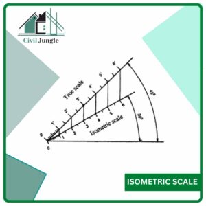
The true shape of the triangle DAB is represented by the triangle DPB. The extent of reduction of an isometric line is easily found by the construction of a diagram known as isometric scale in engineering drawing.
For this, reproduce the triangle DPA as shown in the show below figure-3. Mark the divisions of true length on DP. Through these divisions, draw vertical lines to get the corresponding points on DA.
The divisions of the line DA give dimensions to isometric scale. In the triangle ADO and PDO at the show above figure-2 ( An Isometric Cub), the ratio of the isometric length to the true length,
i.e., DA/DP = cos 45° /cos30° = 0.816
The isometric axes are reduced in the ratio 1:0.816, i.e., 82% approximately.
Also, read: What Is Inverted Beam | Advantages of Inverted Beam | Purpose of Inverted Beam
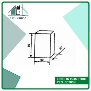
Lines in Isometric Projection
The following are the relations between the lines in isometric projection which are evident from the show above figure-2 ( An Isometric Cub)
- Understanding the difference between isometric view and isometric projection can be seen in how the lines which are parallel to the object are parallel at the isometric projection.
- Vertical lines on the object appear vertical at the isometric projection.
- Horizontal lines on the item are drawn at an angle of 3 0° with the horizontal at the isometric projection.
- A line parallel to an isometric axis is called an isometric line, and it’s fore-shortened to 82 percent.
- A line that’s not parallel to any isometric axis is known as the non-isometric line, and the extent of the fore-shortening of non-isometric lines is different if their inclinations with the vertical planes are different.
Isometric Projection Views
a – Isometric Projection
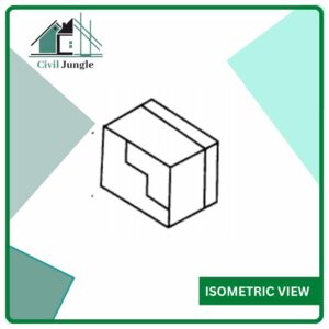
Shows in below Figure (a) rectangular block in pictorial form and Shows in below Figure (b), the steps for drawing an isometric projection using the isometric scale.
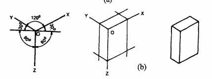
b – Isometric Projection
Also, read: How to Building Construction Process Step by Step
Useful Article for You
- Zero Force Members
- How Much Does a Yard of Concrete Weigh
- Cmu Wall Meaning
- Gradient Road
- Budget Sunroom Ideas
- What Is Gypsum Board
- Types of Vaulted Ceilings
- Well Points
- How Does Baking Soda Remove Blood from Carpet
- What Are Forms in Construction
- How Heavy Is Dirt
- Tender Meaning in Architecture
- Dark Olive Green House
- Cast in Place Concrete
- Lean to Roof
- How Tall Is an Average Door
- Grade Beam Foundation
- Window Sill Height
- Concrete Cold Joint
- Types of Traps
- Types of Pipe
- Wood Supporting Beams
- Finishing Plaster
- Home Depot Scrap Wood
- Lvl Beam Size Calculator
- Structural Shell
- Curb Types
- Msand
- Optimum Dry Meaning
- Disadvantages of Low-E Glass
- Bridge Abutment Definition
- Build Materials List
- Composite Masonry Wall
- Is Cedar a Hardwood or Softwood
- Modified Proctor Test
- Physical Properties of Sand
- Sugar in Concrete
- Crane Machine Construction
- Types of Gable Roofs
- Door Frame Types
- How Much Does 55 Gallons of Oil Weigh
- Dog Leg Stairs
- Concrete Salt Finish
- Westpoint Bridge Builders
- Types of Porches
- Hempcrete Disadvantages
- Roof Pitch Types
- Types of Weirs
- Asphalt Floor
- Dutch Roof
- #6 Rebar Weight Per Foot
- Prizmatic Compass
- Bond Break Concrete
- Poured Concrete Wall Cost Calculator
- How Many 60 Lb Bags of Concrete in a Yard
- Wood Fence Post Spacing Chart
- Falsework
- Design of Building Structures
- Topping Slab
- Types of Cinder Blocks
- Fresh Concrete
- Door Colors for Red Brick House
- Clear Cover Concrete
- Tiles Brand
- Cement Consumption in Plaster
- Aggregate Density Kg M3
- Weight of Concrete Slab Calculator
- Is Clay Smaller Than Silt
- Bad Concrete Work
- Stepped Foundations
- Residential Construction Cost Estimator Excel
- Different Construction Trucks
- Septic Pump Replacement Cost
- Dead Load Calculator
Isometric Drawing
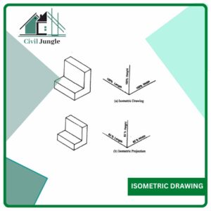
Drawing of objects are seldom drawn in true isometric projections, since using an isometric scale is inconvenient.
Instead, a convenient way, known as isometric drawing with dimensions, in which the foreshortening of lengths is ignored and actual or true lengths are utilized to obtain the projections, known as isometric drawing, or isometric perspective is normally utilized.
This is advantageous because the measurement could be made directly from a drawing. The isometric drawing of the figure is slightly larger (approximately 22%) than the isometric projection.
Since the proportions are the same, the increased size doesn’t affect the pictorial value of this representation, and at the same time, it might be done quickly.
Shows in below a figure the difference between isometric drawing and isometric projection.
- Steps to be followed to make an Isometric drawing from orthographic views are given below
- Study the given views and note the principal dimensions and other features of this object.
- Draw the isometric axes (a).
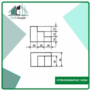
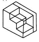
a- Otrhographic View
- Mark the principal dimensions to-their true values along the isometric axes (b).
b- Isometric View
- Complete the housing block by drawing lines parallel to the isometric axes and passing Through the above markings (c).
c- Isometric View
- Locate the principal corners of all the features of the object on the three faces of the Housing block (d).
d- Isometric View
- Draw lines parallel to the axes and passing through the above points and obtain the isometric Drawing of this object by darkening the visible edges (e).
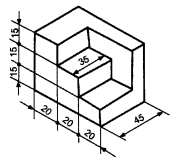
e- Isometric View
Definition of Isometric Drawing
Isometric drawing, also called isometric projection, method of graphic representation of three-dimensional objects, used by engineers, technical illustrators, and, occasionally, architects.
What Is Isometric Scale?
An isometric scale can be used to draw correct isometric projections. All distances in this scale are 2/3 × true size, or approximately 80% of true size. Figure 3.40a shows an isometric scale.
Isometric Drawing
An isometric drawing is a type of 3D drawing that is set out using 30-degree angles. It’s a type of axonometric drawing in which the same scale is used for every axis, resulting in a non-distorted image.
Isometric View
Isometric projection, which provides an isometric view meaning, is a method for visually representing three-dimensional objects in two dimensions in technical and engineering drawings. It is an axonometric projection in which the three coordinate axes appear equally foreshortened and the angle between any two of them is 120 degrees.
Isometric Projection Drawing
Isometric projection, which is crucial for creating an isometric view in engineering drawing, is a method for visually representing three-dimensional objects in two dimensions in technical and engineering drawings. It is an axonometric projection in which the three coordinate axes appear equally foreshortened and the angle between any two of them is 120 degrees.
Like this post? Share it with your friends!
Suggested Read –
- How to Find House Construction Cost
- Building Estimation Step by Step In Excel Sheet
- What Is Development length | What Is Development Length of Bars
- What Is Slab Beam / Hidden Beam / Concealed Beam | Advantage and Disadvantage
- What Is Unit Weight | What Is Density | What Is Unit Weight Material | Unit Weight Building Materials
- Density of Cement Sand and Aggregate | Cement Density | Sand Density | Aggregate Density | list of Density

Effectively concept explanation.
Few more examples ( drawings) are well appreciated as, it will help to clear the concept in depth.